Here is a quick and dirty tutorial for writing data and setting fuse bits on an AVR microcontroler using Ubuntu. All details in this post are related to the Atmega8-16PU, for other versions you should relate to the data sheets for the relevant specifications. First we need to get the necessary development tools:
*Warning: The data pins (1,2) should have a 1k resister in line, this is to stop you from killing either your LPT port, AVR, or both. It will work without just make sure you have it wired 100% correct. 
 Run the following to test the connection:
# sudo apt-get install gcc-avr avr-libc gdb-avr avrdudeNow we need to create a cable to go between the LPT port on your PC and the AVR micro-controller:
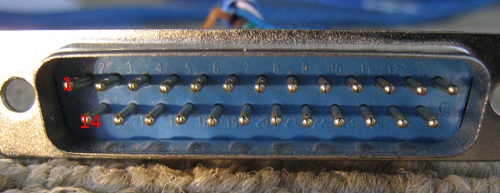
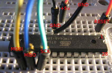
| DB25 Male | AVR |
| Pin 1 | SCK |
| Pin 2 | MOSI |
| Pin 11 | MISO |
| Pin 16 | RESET |
| Pin 21 | GND |

 Run the following to test the connection:
# sudo avrdude -p m8 -P /dev/parport0 -c dapaYou should receive back:
avrdude: AVR device initialized and ready to accept instructions
Reading | ################################################## | 100% 0.00s
avrdude: Device signature = 0x1e9307
avrdude: safemode: Fuses OK
avrdude done.  Thank you.
If you receive:
avrdude: AVR device not responding
avrdude: initialization failed, rc=-1
         Double check connections and try again, or use -F to override
         this check.
Then something is wrong and you should check all your connections. Now to Test out some code you can try this example:
/* * blink.c */Save as blink.c Now in the same directory save the following Makefile:
#include <avr/io.h> #include <util/delay.h> #define LED PD4
int main(void) { // define pd4 as output DDRD |= (1 << LED); while (1) { PORTD |= (1 << LED); // switch on _delay_ms(1000); PORTD &= ~(1 << LED); // switch off _delay_ms(1000); } return 0; }
MCU=atmega8 AVRDUDEMCU=m8 CC=/usr/bin/avr-gcc CFLAGS=-g -Os -Wall -mcall-prologues -mmcu=$(MCU) OBJ2HEX=/usr/bin/avr-objcopy AVRDUDE=/usr/bin/avrdude TARGET=blinkSo now using the makefile we are going to create a .hex file of the c code above and write it onto our chip:
program : $(TARGET).hex $(AVRDUDE) -p $(AVRDUDEMCU) -P /dev/parport0 -c dapa -U flash:w:$(TARGET).hex
%.obj : %.o $(CC) $(CFLAGS) $< -o $@
%.hex : %.obj $(OBJ2HEX) -R .eeprom -O ihex $< $@
clean : rm -f *.hex *.obj *.o
# sudo makesucessful output:
/usr/bin/avr-gcc -g -Os -Wall -mcall-prologues -mmcu=atmega8 -c -o blink.o blink.c /usr/bin/avr-gcc -g -Os -Wall -mcall-prologues -mmcu=atmega8 blink.o -o blink.obj /usr/bin/avr-objcopy -R .eeprom -O ihex blink.obj blink.hex /usr/bin/avrdude -p m8 -P /dev/parport0 -c dapa -U flash:w:blink.hexAttach a LED to PD4 with a resister in line and the LED should light up and flash. Written by: Jason Smith
avrdude: AVR device initialized and ready to accept instructions
Reading | ################################################## | 100% 0.00s avrdude: Device signature = 0x1e9307 avrdude: NOTE: FLASH memory has been specified, an erase cycle will be performed To disable this feature, specify the -D option. avrdude: erasing chip avrdude: reading input file "blink.hex" avrdude: input file blink.hex auto detected as Intel Hex avrdude: writing flash (138 bytes): Writing | ################################################## | 100% 0.05s avrdude: 138 bytes of flash written avrdude: verifying flash memory against blink.hex: avrdude: load data flash data from input file blink.hex: avrdude: input file blink.hex auto detected as Intel Hex avrdude: input file blink.hex contains 138 bytes avrdude: reading on-chip flash data: Reading | ################################################## | 100% 0.03s avrdude: verifying ... avrdude: 138 bytes of flash verified avrdude: safemode: Fuses OK avrdude done. Thank you.
rm blink.obj blink.o


